How to Build 4-Link Bars
Since not all applications will have a kit available, Speedway Motors sells the parts needed to build your own 4-link bars. My project truck is one of those applications where I would have to do some fabrication to get exactly what I wanted. Here’s a guide to help you if you ever need to build your own links of any kind.
How to Determine Cut Length For 4-Link Tubes:
The general rule is that you must have at least as much thread inside the tube as the diameter of the threads. So in my case using 3/4-16 rod ends, I must have at least 3/4” of an inch threaded inside to remain safe.
When building your 4-link bars (or any other type of adjustable links) you want to have them in the middle of the adjustment range so you can have enough adjustment to set up your suspension. My goal is to end up with 31.75” center to center length 4-links, in the middle of the adjustment range.
Here’s the math I used to figure out the tube cut length:
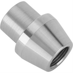
(3/4-16 Threaded 4-Link Rod End has 1.950” threaded length)
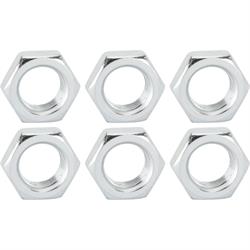
1.950” total threaded length - .750” minimum threaded into tube - .4375” thick jam nut = .7625” is the maximum thread sticking out from the jam nut allowed, and still have .750” threaded inside the tube
.7625”/2 = .3812” is the middle of the adjustment range
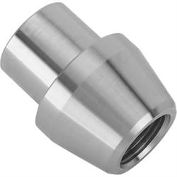
Here you can see the finished 4-link bar with the rod end adjusted to the middle of the allowable stick out.
With the rod end and jam nut adjusted to the middle of the adjustment range, measure the center of the hole to the end of the weld bung, and I got 2.650”. I will add .100” of gap between the weld bung and the tube when I weld to get good penetration, so this measurement ends up being 2.750”.
2.750” x 2 = 5.50” 31.75” center to center 4-link length -5.50” =26.25” cut length for the tube
Weld & Assemble Links
After I cut the 1.375” o.d. X .1875” wall 1026 DOM steel tube I used for these links, it was almost time to weld them up. Before welding, I chamfered the ends of the tube to allow for good weld penetration, and I also like to drill a couple of holes so I can also rosette weld the sides of the weld bung. I used a 3/8” step drill bit to drill through both sides of the tubing.
After drilling the holes, there was a little burr left from the drill bit. I used a small 3/4” flap wheel sander to clean up the inside of the tubing.
The weld bung slides nicely into the 1.0” i.d. tubing. At this point, the links are ready to be welded.
After TIG welding the bungs to the tube, I used my grinder to level the welds and then used a dual action sander with 120 grit to smooth the tubes out.
With my 4-link bars all welded up, I am finally ready to get my rear suspension setup and in place.