Crimp vs Solder | How to Solder & Crimp Automotive Wires
Crimp vs Solder: Best Automotive Wiring Practices
Get a few of your car friends together for a bench racing sesh and you’re bound to give each other some playful opposition on subjects like “Ford vs Chevy” or “manual vs automatic” but when it comes to discussing whether automotive wiring should be crimped or soldered, well for many, them’s fighting words! We get it, for those that regularly work with automotive wiring they are very opinionated and passionate about their preferred wiring process for harness connections. But let’s not fight friends! We feel that when it comes to crimp vs solder, both have their place in automotive wiring work, be it a full install of your best classic car wiring harness, building a custom wiring harness from scratch, or simply installing a new stereo or set of gauges. Read on to hear our thoughts on crimp or solder, when and where to use each process, how to solder a wire, a crimping how to, and more!
We’re discussing soldering vs crimping: advantages & disadvantages in automotive use here exclusively. When it comes to crimp or solder, there are strong advocates in each camp. Crimping, when done properly and with the right tools, many feel is the preferred method of connecting wires in automotive wiring harnesses. Still others feel that if it isn’t a soldered connection with shrink wrap the connection is garbage and will fail over time. Are there truths to both statements? Yes, but the rub lies in the “when done properly” aspect of both crimping and soldering. A poor crimp or a bad solder joint will create a bad connection electrically and more than likely fail prematurely. There’s little doubt that crimping is easier and faster, so that makes it the main connection option for many since the process can be picked up quite easily. Soldering, on the other hand, takes more skill, time, and equipment, but once you master how to solder wires you can use it for all sorts of electronic work. So, is crimping better than soldering? Read on for our thoughts.
Are Crimp Connectors Reliable?
The crimping of a wire, either to another wire or to wire terminal for a connector, involves using a crimping tool to mechanically apply pressure to a wire terminal over a bare wire end, creating a solid mechanical bond when performed properly. Crimped connections are usually very dependable in harsh environments or where high vibration occurs. This can be in motorsports where there are high g-loads and vibrations, or where movement occurs in a road vehicle, such as opening of doors, hood, and trunk for example. Crimp connections are generally easy to use and can be installed quickly in most instances, though it is imperative that quality crimping tools are utilized to create a strong crimp that is repeatable for all crimp connections being placed into service.
Wire Crimping Pros & Cons
Pro: Reliable: Strong, durable connections.
Pro: Easy to Install: Quick and straightforward with the right tools.
Pro: Durable: Withstand vibration and mechanical stress.
Pro: Consistent Quality: Proper crimping ensures uniform performance.
Pro: No Heat Required: Safer than soldering, as it avoids heat damage.
Pro: Versatile: Suitable for various wire and cable types.
Con: Tool Dependency: Requires specific, sometimes costly tools.
Con: Skill Requirement: Needs some expertise for reliable connections.
Con: Initial Cost: High-quality tools and connectors can be expensive.
Con: Limited Reusability: Generally, not reusable once crimped.
Con: Potential for Errors: Incorrect crimping can lead to failures.
How to Crimp Wires Properly
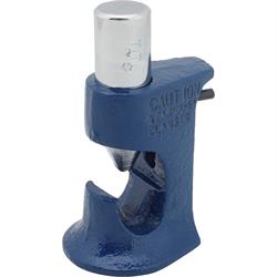
As we’ve stated previously, when performed properly a crimp connection is a very solid and reliable way of connecting two wires together or terminating a wire with a terminal end such as a ring terminal for a ground wire. To produce the best crimp possible and perform a proper crimp repeatedly there are a few things to keep in mind as part of a how to crimp a wire connector primer. First is the crimping tool itself. Don’t cut corners here. The job is best completed with a quality pair of automotive wire crimpers.
We prefer ratcheting wire crimpers, as they provide the perfect crimping pressure no matter the terminal size and often have replaceable jaws to allow you to crimp different connector/terminal types including insulated and non-insulated terminals, Weather Pack-style terminals, and even spark plug wire terminals. Regular crimping tools can allow over-crimping of a terminal, nearly severing the terminal and wire connection. Of course, under-crimping is an issue as well with those with low hand strength, causing wire pull out. This is why we recommend a ratcheting crimper to do the job right every time if you want to learn how to crimp wires together.
Along with the correct crimping tool is using the correct type of terminal for the jaws the tool is designed for. You can’t effectively crimp a Weather Pack-style terminal with a crimping tool designed for the classic red/blue/yellow insulated wire terminals. You must understand how to use crimp wire connectors themselves, including their wire size specs and more, as the crimping tool is only part of the process. The proper size and type of connector or terminal will be dictated by the wire size (or number of wires) and what you are trying to do, such as connect two wires together, add a ring terminal, or a spade terminal for a relay for example. Some instances will dictate insulated terminals, while others can use uninsulated terminals. This is another reason we highly recommend ratcheting crimpers with the option for different jaw sets. A good tip we learned a long time ago was to use uninsulated terminals along with adhesive lined automotive shrink tubing. This provides a clean OE appearing connection with lower overall diameter or bulk being added to the wire connection and you don’t have a sea of red/blue/yellow connections all over your engine compartment.
Besides the proper tool and terminal, preparing the wire is also key to a solid crimp connection. You will need to carefully strip the wire’s insulation away using automotive wire strippers to expose the correct length of bare wire strands to insert into the crimp terminal. This is dictated by the type and size of the terminal (wire strip lengths are often listed on the packaging). Much like the ratcheting crimpers, we recommend automatic wire strippers where you can adjust the depth setting and one squeeze of the handle safely strips away the insulation without cutting or nicking any of the wire strands.
With the wire prepared properly it can then be inserted into the crimp terminal. Most terminals have a wire stop, but if not ensure your wire isn’t inserted too far into the terminal where the insulation blocks the connection between the wire and the terminal body. Using the proper jaw of your crimper, place the crimp terminal into the crimping tool and crimp the connection. Confirm the wire is crimped and secured within the terminal. A strain test by pulling on the connection will also confirm the connection is solid. Lastly, use an automotive electrical tester to confirm the connection’s electrical continuity and resistance values are within spec. That is essentially it for a crimping how to. Easy huh? Oh, and if you’re wondering how to crimp battery cables, you’re working with the same essential steps, just the wire and terminals you’ll use are larger, as is the crimping tool.
How to Splice Wires with Crimp Connectors
So far, we’ve discussed connecting two or more wires together with a crimp connection or adding a crimp terminal to a wire end. However, in some instances you may need to add a wire to an existing wire circuit, such as tapping into a key switched power wire. This is called a wire splice. You can perform a wire splice using crimping tools and solderless crimp connectors if care is taken to ensure the connection is made correctly. First, identify where the splice is best made into the existing wire. It is important to understand where to crimp wire connectors into your existing harness. Then, you’ll need to determine if you want to cut the existing wire to make the splice or if you want to “T” into the wire using a t-tap or similar connection. The most secure connection will be with the use of a butt splice crimp terminal and cutting the original circuit’s wire, as T-taps, in our opinion, should only be used for temporary or emergency wiring needs. However, we do understand that not everyone wants to cut into a perfectly good wiring harness. For those instances we recommend direct wire to the ignition switch or battery. It’s a little more work, but you’re not cutting your expensive or original wiring harness.
To make the splice you’ll need a quality pair of wire cutters, crimpers, and the appropriate wire connector. When adding a wire to a circuit like this you can use a larger connector to fit two wires into and then resize the opposite end for inserting the single wire. You can also, in some cases, find wire connectors sized differently on each end for such projects. These are called “step down” butt connectors and while they are designed to connect two different wire sizes, they provide extra room for that add-on wire circuit as well. Lastly, some heat shrink wrap is a good idea for connections that will reside in the elements (engine bay, under the car, and so on).
To make the actual connection, first identify where it will be best to connect your new circuit and how you wish to connect it (a butt connector or T-tap). Once you’ve confirmed the wire circuit you’ll use (switched 12V or constant 12V, amp capacity of the circuit, etc.) via your favorite electrical tester, disconnect the battery. For the butt connection method, you will need to cut the existing circuit, strip the wire ends of the existing circuit wires and do the same for the add-on circuit. Combine one of the existing circuit wires with the new wire by twisting together and inserting it into one end of the butt connector and crimp properly. Do the same with the remaining original circuit wire on the opposite end of the butt connector and test the connection for pull strength. If you’re going to use heat shrink, be sure to install it over the last wire before crimping (sort of like adding the tube nut before flaring a brake line!). Reconnect the battery and test the circuit and connection.
For a T-tap style connection you simply place the T-tap over the wire you have identified earlier and crimp it in place. Most T-tap connections utilize a built in insulation cutting design, so no wire stripping is usually required. Additionally, T-tap connections and the like do not require traditional crimpers but are closed around the wire and locked into place via pliers. The T-tap, once secured over the wire, is ready to accept the new wire circuit addition by way of an insulated spade terminal crimped onto the new wire being installed. Again, we want to note that we consider a T-tap or any sort of insulation displacement connector that does not require stripping the insulation to be a temporary or emergency connection for most cases. Yes, we said in most cases. You certainly don’t want to use a T-tap or other such connector to power your high amp cooling fan or electric fuel pump, but we can see where they might be OK for something low amp in an interior wiring application, such as adding LED light strips, or perhaps a USB port to charge your cell phone. That sort of thing.
How to Crimp Connectors Without Crimper
If you’re in a bind and having to come up with a way to crimp a wire repair together for a roadside emergency for yourself or a fellow enthusiast, we have some tips for you on how to crimp wire connectors without a crimper. While you may not have a proper wire crimper or even a wire stripper in your emergency tool kit (though we encourage you to do, along with terminals, electrical tape, replacement fuses, and more for wiring issues that pop up), you most likely have a pair of pliers in your kit and at least one flat head screwdriver. These two tools can help you with how to crimp wire terminals for an emergency wire crimp repair in a pinch.
To strip the wire insulation away for use with a butt connector or other wire terminal it is best to use a wire stripper, but without one you can use a pocket knife, the inner most portion of the pliers’ jaws (and some pliers have built in wire cutters that can strip insulation provided you don’t cut all the way through), or any sharp object with some care and attention. Once the wire is stripped it can be inserted into the terminal. To complete the crimping procedure, use the pliers (needle nose offers a more precise crimp, but standard slip joint pliers will work in a pinch as well) to crimp the terminal’s barrel around the wire. To provide additional security, place the tip of the flat blade screwdriver into the crimp you just made and apply pressure or use a hammer or other object as a hammer to further crimp the connection. Wrap the emergency repair with some electrical tape and secure as necessary with some tie wraps.
Best Crimp Wire Connectors
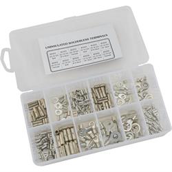
When crimping a wire terminal to a wire your crimp operation is only going to be as good as the tools you use to prepare and crimp the wire connection and the wire connector or terminal itself. This is most definitely a case of getting what you pay for. Those big bags of bulk wire crimp connector types you see at the swap meet may seem like a deal, until you use them, and you have inconsistent crimps, poor retention strength, and soft metal construction that corrodes and fails. This is why we highly recommend and sell Pico brand butt connectors and wire terminal assortments. The Pico brand products are made from premium materials, are easier to crimp, and hold wires securely for a positive connection that is worry free. We offer Pico connectors in all popular automotive wire gauge sizes for butt splice connections as well as in convenient terminal assortment kits, including versions with solder seal and/or heat shrink insulators.
Pico Wire Terminal Benefits:
- Made from high-quality, corrosion-resistant materials, ensuring long-lasting connections.
- Robust construction withstands mechanical stress, suitable for automotive, marine, and industrial applications.
- Designed for easy and efficient installation, reducing time and effort.
- Versatile for various wire gauges and types, with clear instructions for use.
- Provide a strong hold on wires, minimizing the risk of loose connections.
- Precision engineering ensures consistent and reliable performance.
- Comprehensive range of connector solutions, including butt connectors, ring terminals, spade terminals, and more.
- Color-coded options by wire gauge simplify the selection process.
- Available with built-in heat shrink tubing for additional insulation and protection.
- Priced competitively for the quality and features offered.
How to Use Heat Shrink Butt Connectors
A popular option from Pico are heat shrink sealed butt connectors and terminals. These are wiring connectors with a typical butt splice terminal inside, or a ring terminal, etc., but the nylon colored outer insulator has been replaced with a heat shrink material. Pico heat shrink connectors are still color coded to wire gauge size for easy identification but provide a weather tight seal to the elements for use outside of the passenger compartment. These terminals are perfect for under hood or chassis mounted electrical items like cooling fans, fuel pumps, lighting, and more that might see dirt and rain. Due to the additional strength and support the heat shrink provides, this style of terminal generally has great pull strength results and provided the connections are crimped properly will have acceptable electrical continuity and resistance values that will not be affected by moisture. Using this style of terminal is easy, as it is no different than what you’ve already learned with how to crimp a wire connector except for adding the last step of heat shrink sealing the connection. Once you learn how to use heat shrink butt connectors and the step/time it saves you might never go back to standard vinyl insulated butt connectors!
Pros and Cons of using a heat shrink crimp connector:
Pro: Provides excellent insulation and sealing against moisture and contaminants.
Pro: Offers a secure and durable connection once properly installed.
Pro: Easy to use and install, requiring only basic tools.
Pro: Suitable for a wide range of wire gauges and types.
Con: Requires a heat source (heat gun or torch) for activation, which may not be readily available in all situations.
Con: Can be slightly bulkier than traditional butt connectors due to the heat shrink tubing.
Con: May take slightly longer to install compared to non-heat shrink connectors.
Automotive Wire Soldering
To this point we’ve focused on crimping wiring connections, but a good “this vs that” conversation isn’t much good without the “that” aspect. So, let’s talk about soldering. Soldering is a process that uses heat to melt an electrically conductive metal alloy and applying it to the junction of two or more wires or to a wire end for installation of a metal electrical terminal. Soldering with automotive solder kits is another mechanical wiring connection option, although it does take a specific tool and some experience to create a proper solder connection. Soldering may be a good option for certain aspects of a wiring repair or total vehicle wiring job. Sensitive electrical circuits, such as computer sensor connections, or electrical circuits that may be critically affected by resistance values are good candidates for solder connections. Soldering is a great wiring connection option if the circuit warrants it, and the conditions are favorable. You’re not usually going to be able to perform a roadside emergency wire repair using solder for example.
Wire Soldering Pros & Cons
Pro: Reliable Connection: Soldered connections are generally more dependable and durable than other methods, such as crimping, as they provide a strong physical and electrical bond.
Pro: Low Resistance: Soldered joints have low electrical resistance, ensuring efficient transfer of electrical current and minimizing voltage drop.
Pro: Permanent: Once properly soldered, the connection is permanent and less susceptible to coming loose or corroding over time.
Con: Time Consuming: Soldering can be more time-consuming than other methods, especially for large wiring harnesses with numerous connections.
Con: Skill Required: Proper soldering technique requires skill and practice. Poorly soldered joints can lead to weak connections, cold joints, or damage to components.
Con: Heat Sensitive Components: Some electronic components are heat-sensitive and can be damaged by excessive heat from soldering.
What Solder for Automotive Wiring
Like any topic, you will find multiple choice answers are common. The same can be said for asking what the best solder is to use for the typical wiring found in a 12V automotive application. Many will say rosin-core solder is the only option for automotive wiring. While we tend to agree with that statement for common 12V electrical circuits, there are a few other solder alternatives that we’ll list below. It is up to you to determine the best solder for the application, however for 95 percent of the automotive wiring you’ll be working on, rosin-core is going to do well for you.
Commonly used Solders include lead-free, rosin-core, and silver solder. Below are a few notes on each and their main usage:
Lead-Free Solder:
- Contains various combinations of tin, copper, silver, and other metals.
- Compliant with environmental regulations and safer to use.
- Offers good conductivity and is suitable for many automotive applications.
Rosin-Core Solder:
- Contains a flux core, which helps to remove oxidation and improve solder flow.
- Suitable for general automotive wiring tasks.
- Provides good electrical conductivity and is easy to work with.
Silver Solder:
- Contains a higher percentage of silver, offering superior conductivity.
- More expensive than traditional solders.
- Ideal for high-performance automotive applications where conductivity is critical, such as in audio systems, sensors, computers, or high-power circuits.
There are solders on the market that should not be used in automotive wiring as well. We won’t dwell on these but will note them below, so you know to stay away from them and leave them in your toolbox for other household use.
Lead-Based Solder:
- Traditional solder containing lead and tin.
- Provides excellent conductivity and is easy to work with.
- Not recommended for automotive use due to environmental concerns and potential health hazards associated with lead exposure.
Acid-Core Solder:
- Contains a flux core with acid, primarily used for plumbing applications.
- Not suitable for automotive wiring as the acid residue can corrode electrical connections over time.
How to Solder Wires Properly
Soldering wires together or soldering a terminal to a wire end takes practice and a bit of patience. It is best to use a bench top or other work area for soldering as you learn soldering iron basics, but with experience you can certainly solder directly on an installed harness or electrical device in a vehicle. Soldering is also one of the preferred ways to join two different sized wires, such as adding a 16 gauge add-on circuit to an 8-gauge power wire. The process of soldering wiring begins much like using a crimp terminal. You’ll want to determine where to make the splice or where the wiring is going to be lengthened, terminal added, and so forth and strip the wire insulation away. For older wiring where there may be some oxidation to the copper strands it is optional to use steel wool, sandpaper, or other methods to clean the copper wire strands in preparation for soldering.
Next you will want to further prepare the wire for the upcoming solder application by applying solder flux to the copper wire strands. This is probably another argument that we don’t have the space to get into, but some say the flux in “rosin core” solder is enough, while others swear your solder won’t flow properly or stick without adding flux to the wires first. What do we say? Try both ways and see what your success rate is on practice wiring. You’ve got to learn how to solder anyway, right? The extra flux application step takes mere seconds here, so it can’t hurt and only help make a better connection.
With your copper wire strands fully prepped you will next “tin” the wire ends. Tinning is the process of applying heat to the bare wire end(s) via your soldering iron and feeding a small amount of solder into the wire strands to coat the wires evenly. This helps prevent fraying and improves conductivity. It also makes soldering two wires together that much easier. Tinning your wire strands does not require a lot of solder. You don’t want the solder wicking up inside the wire’s insulation, making a stiff wire section that is more susceptible to failure due to vibration.
Now comes the fun part, joining the wires together (or the terminal to the wire end). Position the tinned wire ends so that they are parallel to each other. Often a small vice or a “third hand” is helpful in securing the wires for soldering. Again, you will utilize your soldering iron to heat the wires, but this time you are heating the wires until the tinned solder melts, at which point you will “flow” additional solder into the wire joint as needed. Just like when you were tinning the wires initially, you do not want to apply an excessive amount of solder, which can make a bulky connection or wick up the wiring under the insulation, creating a brittle wire. Lastly, if the wires you are connecting do not have an accessible end to install heat shrink sleeve to, then be certain that you add the shrink sleeve before soldering the wires together. We also caution that the shrink sleeve should be far enough away from the solder work area to not be affected by the heat and begin to shrink. Let the solder joint cool completely before moving the shrink sleeve into place over the solder joint.
After the joint or wire end/terminal has had sufficient time to cool, inspect the joint for full solder penetration and tug on the joint to ensure it has a firm connection. Circuit test the joint to verify conductivity and resistance is within range and if all checks out then finalize the connection by heating the shrink sleeve in place over the solder joint to fully protect the joint from moisture and other contaminants that may affect the wire joint. Congratulations, you just learned how to solder two wires together and made a great solder joint that will last.
Hot Take: Crimped vs Soldered Connections
So, let’s recap our pros and cons of crimp vs solder here and we’ve provided a nifty decision matrix graphic as well to help guide you in your wire connection efforts.
Crimped Connections Pros & Cons:
Pro: Quick and easy to make.
Pro: Can be done without special tools, though crimping tools are recommended for better results.
Pro: Provide mechanical strength and strain relief when done properly.
Pro: Suitable for high vibration environments, such as automotive applications.
Con: Prone to corrosion if not properly sealed.
Con: May not offer the same level of conductivity as soldered connections.
Con: Requires proper selection of crimps and tools for reliable results.
Soldered Connections Pros & Cons:
Pro: Provides excellent electrical conductivity.
Pro: Offers a strong and permanent bond when done correctly.
Pro: Can be more aesthetically pleasing and compact compared to crimped connections.
Pro: Less prone to corrosion when properly insulated.
Con: Requires more time and skill to make compared to crimped connections.
Con: Excessive heat can damage components or insulation.
Con: May become brittle over time, especially in high vibration environments.
When should you use one method versus the other?
Crimped Connections:
Ideal for applications where quick installation, mechanical strength, and resistance to vibration are crucial. They are commonly used in automotive wiring, where reliability under harsh conditions is essential.
Soldered Connections:
Recommended for applications where excellent electrical conductivity, permanence, and aesthetic appearance are priorities. They are commonly used in electronics, audio systems, and applications where vibration is minimal.
Crimping vs Soldering Decision Matrix

Best Automotive Crimping Tools
There are many crimping tools on the market. Most are familiar with the standard manual hand crimpers. These crimpers are like a pair of pliers but have special crimping jaws cast or machined into the head of the tool. These are commonly used for insulated crimp connectors and can often be had in convenient kit form with a selection of crimp terminals. The one issue with a hand crimper is that it relies on overall hand strength, which means it is easy to under or over crimp a solderless terminal. They are a decent enough starter tool or can be tossed into a roadside emergency tool kit, but there are better options.
There are some instances where a manual crimper may be a better solution, however. In tight spots, such as under dash work, or repairing a damaged taillight wire in a trunk stuffed full of road trip gear, a mini hand crimping terminal tool might be the best solution. Speedway Motors carries a 3-piece crimper/stripper/cutter tool kit where each tool is just over five inches long. We’ve used a similar set for many years now, and while not the first crimper tool we reach for in our toolbox, when warranted it is the perfect solution.
Ratcheting crimpers are by far the preferred method for crimping solderless butt connectors and other terminals. These crimping tools feature a ratcheting handle set that allows you to crimp the terminal without over crimping and possibly damaging or cutting through the terminal. You will find many different ratcheting crimper offerings, but our favorites are the type that offer interchangeable crimping jaws which allow you to use the same ratcheting crimper for solderless insulated terminals, solderless non-insulated terminals, open barrel terminals, Weather Pack-style terminals, and even spark plug wire terminals.
If you do a lot of wire harness building, EFI wiring, or other specialty wiring then you may prefer a dedicated wire crimper for that specific terminal type, such as Weather Pack-style terminals or open barrel terminals. We offer several options for these terminal specific crimper tools if your primary focus is benchtop harness building or other such terminal work where you’re working with a specific terminal design exclusively.
Best Automotive Soldering Tools
If you feel soldering is the best solution for your wire connection or terminal installation, you’ll need the right soldering tools to get the job done. These tools include soldering irons, solder, flux, and more to make a proper solder joint or to solder a terminal to a wire end. The primary need is of course a soldering iron. You’ll want to determine if you are best served by a pencil-style soldering iron or a larger soldering “gun” for your needs. A small soldering iron is easier to use in tight spots and is lighter in the hand. These can be had in cordless and corded styles, as well as built into soldering stations used for benchtop work. Soldering stations, popular with electronic hobbyists, allow custom temperature adjustments, multiple tip styles and more. Check your local hobby shop out if that’s a direction you want to investigate. For most basic automotive electrical soldering a standard soldering iron works just fine. The cordless ones are great for in-car work as well.
Of course, the soldering iron is just the beginning of your wire soldering journey. You’ll need flux, solder, tip cleaner, a heat gun or small torch for your heat shrink sleeve, and more. You’ll find some of the soldering iron kits we offer include the tip cleaner, and rosin-core solder as part of their kit, which is a great start to your soldering needs. However, the tip cleaner should be considered a wear item requiring periodic replacement, and of course your solder is a consumable product, so be certain to have enough on hand to not run out mid-project.